Honda Silver Wing Scooter Forum


HomeHome  GalleryGallery  FAQFAQ  SearchSearch  RegisterRegister  Log inLog in  
Search


Display results as :
 
Rechercher Advanced Search
Latest topics
» checking the oil
OEM flasher bypass harness I_icon_minitimeby COMick Yesterday at 9:46 am

» Hobbies? (Besides maxi scooters, of course?)
OEM flasher bypass harness I_icon_minitimeby Erdoc48 Yesterday at 6:46 am

» Modifying Honda Silver Wing 600
OEM flasher bypass harness I_icon_minitimeby Frenchy Sat May 04, 2024 4:11 pm

» Poor man’s Power Commander: IAT Sensor modification (Intake Air Temp Sensor)
OEM flasher bypass harness I_icon_minitimeby gavinfdavies Fri May 03, 2024 3:33 am

» Sinko De Mayo
OEM flasher bypass harness I_icon_minitimeby GHM-PM Thu May 02, 2024 7:10 am

» May 2024 forum picture
OEM flasher bypass harness I_icon_minitimeby MikeO Thu May 02, 2024 4:42 am

» Strongly considering a one way ride from Texas to Progreso,Mexico and could use some advice
OEM flasher bypass harness I_icon_minitimeby GHM-PM Mon Apr 29, 2024 10:08 pm

» LF extended back rest
OEM flasher bypass harness I_icon_minitimeby Rzor93 Mon Apr 29, 2024 4:14 pm

» FOR SALE - 2009 Silver Wing
OEM flasher bypass harness I_icon_minitimeby GHM-PM Mon Apr 29, 2024 6:47 am

» Where can I find top-quality electronic tracks?
OEM flasher bypass harness I_icon_minitimeby GHM-PM Mon Apr 29, 2024 6:43 am

Navigation
 Portal
 Index
 Memberlist
 Profile
 FAQ
 Search
free forum


 OEM flasher bypass harness

Go down 
2 posters
AuthorMessage
aaronb
Scooter Rider
Scooter Rider


Number of posts : 18
Location : Houston, TX
Points : 4566
Registration date : 2011-11-28

OEM flasher bypass harness Empty
PostSubject: OEM flasher bypass harness   OEM flasher bypass harness I_icon_minitimeMon Mar 26, 2012 3:19 am

As discussed previously in other threads (here and on other boards), the Silverwing's flasher circuit is embedded into the instrument cluster instead of being a traditional/replaceable unit. Now, I won't pretend to be more intelligent than the Honda engineers, but that's a bone-headed move that makes any service and upgrading difficult at best. If the built-in flasher circuit ever fails (not very likely), then the entire instrument cluster must be replaced. That's just about as annoying as trying to remove the left glove box lid. Mad

I decided to upgrade all of the indicator lights on my scoot to LED's. Unfortunately, the LED's draw too little current for the factory flasher to operate at the correct rate, which leads to the hyper-flash problem (fast flash, like when one of the bulbs is out). Since the factory flasher isn't a replaceable item, the only alternatives that I can fathom are:
  1. Use load resistors, which takes away the benefit of the lower current draw of the LED's, or
  2. Make a bypass harness at the instrument cluster that intercepts the inbound switch wires and outbound signal wires.

I decided to go with option #2 and make the bypass harness because that will let me use an external flasher module and make clean extensions for additional front signal outputs (e.g. mirror signal LED's, etc). This will also give the ability to bridge both left and right circuits to create 4-way hazard flashers. Other possible upgrades on this path could include auto-cancelling signals, audible beeper/buzzer, etc.

The bypass needs to be done at the back of the instrument cluster because that's the only convenient place to intercept the switch wires before the factory circuit and outbound signal wires in the same place. The only drawbacks that I can see are:
  • The factory circuit allows for front running lights (it runs them at about 10.2 volts until a signal is activated, then goes full on/off); the new circuit could certainly incorporate that, but I haven't gotten that far yet.
  • Pilot indicators need to be fed back into the instrument cluster in the OEM locations or somewhere nearby; not sure if I can use the factory turn indicators without powering the whole OEM circuit (they are SMD LED's, directional flow), so additional LED's might need to be drilled in somewhere.

Alternately, the front signal bulbs (BAU15S type) and sockets could be replaced with dual-filament (7443 type) and scrap the low-voltage bit entirely. But again, I haven't gotten that far and that would also require some minor fairing harness changes for the additional signal wire to each side.

I searched for quite a while to locate the exact AMP connectors that are used on the factory harness. The only visible marking on the connectors is "AMP", but no part number. So, after days of searching online catalogs and cross-references, I found the exact OEM part in Tyco Electronic's vast arsenal of connectors.

The male and female connector housings are around USD $1.20-1.80/ea (2 per harness) and the internal terminals and receptacles are around $0.30/ea (56 per harness). The next hurdle is that all of the suppliers for these parts have HUGE minimum order requirements... try 1000-5000 pieces, some are as high as 20K pieces for their minimum. Ouch. Tyco Electronics (Amphenol) was kind enough to send me a few "engineering samples" so I could prototype the harness.

My next step is to get a working sample and then... maybe Dennis could build them if anyone is interested? I could do it, but I'm not properly tooled up for the task. I'm sure Dennis can attest that the tooling is not cheap if you want to do it right. After all, I wouldn't want a poor-quality connection causing my instrument cluster to wink out at random... that would be a Bad Thing.

Well, enough of what I don't have or haven't done yet... here are a few pics of the interior of the instrument cluster where the dreaded flasher bug lives, and others of the male and female connectors needed. Later, I will post the connector pin numbers instead of wire colors because the Honda color codes on the small harnesses are very difficult (stripes, dots, slashes, and bands... whew).

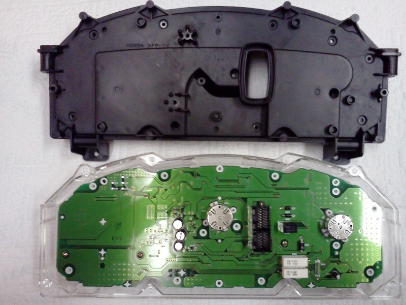
Here is the instrument cluster opened, face-down, showing the back of the circuit board:

OEM flasher bypass harness 2004-f13

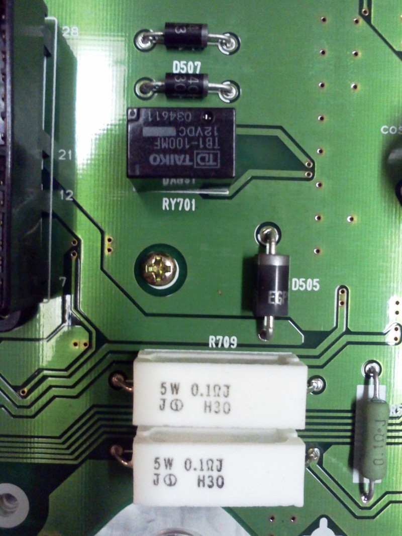
This is a close-up of the flasher relay, diodes, and load resistors for the front running light function (presumed):

OEM flasher bypass harness 2004-f14

This is the back of the instrument cluster. I have annotated the picture with the equivalent TE/AMP connector numbers for wire-to-wire use (the cluster uses a wire-to-board connector, different p/n):

OEM flasher bypass harness 2004-f18

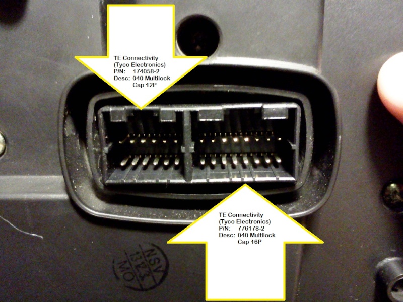
This is a shot of the bike harness connectors for the gauge cluster. Again, I have annotated the picture with the TE/AMP part numbers:

OEM flasher bypass harness 2004-f17
Back to top Go down
https://www.youtube.com/QuasiMotard
aaronb
Scooter Rider
Scooter Rider


Number of posts : 18
Location : Houston, TX
Points : 4566
Registration date : 2011-11-28

OEM flasher bypass harness Empty
PostSubject: Re: OEM flasher bypass harness   OEM flasher bypass harness I_icon_minitimeMon Mar 26, 2012 11:09 am

It was late last night and I forgot to mention that I have already purchased some of the raw components. I found a few suppliers that had the internal pieces for the connectors (the terminals and receptacles) on clearance, so I snapped those up. The housings are the more difficult items to find without making a large purchase.

Here is a list of the part numbers and quantities for each side of the harness:

Bike harness side:
(1) TE/AMP PN: 174058-2 (040 Multi-Lock Cap 12P)
(1) TE/AMP PN: 776178-2 (040 Multi-Lock Cap 16P)
(28) TE/AMP PN: 175063-1 (040 male tab)

Instrument cluster side:
(1) TE/AMP PN: 174045-2 (040 Multi-Lock Plug 12P)
(1) TE/AMP PN: 174046-2 (040 Multi-Lock Plug 16P)
(28) TE/AMP PN: 175062-1 (040 female receptacle)

Here are links to the engineering specs for the plugs and caps for anyone who is interested. If someone is building a harness, then the reference could be useful.

174045-2 040 Multi-Lock Plug 12P
174058-2 040 Multi-Lock Cap Housing 12P
174046-2 040 Multi-Lock Plug 16P
776178-2 040 Multi-Lock Cap Housing 16P

The wires to bypass/intercept are on both connectors. The inbound signal switch wires are in the 12P connector, and the outbound indicator lamp wires are in the 16P connector. Here are the pin numbers (and rough colors, hard to be exact without my notes that happen to be in my shop manual... both missing at the moment).

12P connector:
PENDING...

16P connector:
12 - right-rear signal (light blue, dot)
13 - right-front signal (light blue, white stripe, dot)
15 - left-rear signal (orange, silver stripe)
16 - left-front signal (orange, white stripe, silver bands)

I will update the wire colors and pin numbers above when I find my notes (and shop manual), or the next time I open the front end of the scoot.

If Dennis (or anyone else) is interested in assembling and selling these, I'd be happy to send some of the materials his way. I have about 2000 the female receptacles, 200 of the male tabs, and only 2 sets of the plugs and caps.
Back to top Go down
https://www.youtube.com/QuasiMotard
Cosmic_Jumper
Site Admin
Cosmic_Jumper


Number of posts : 4416
Age : 81
Location : damn near Philadelphia, PA
Points : 10550
Registration date : 2009-06-12

OEM flasher bypass harness Empty
PostSubject: Re: OEM flasher bypass harness   OEM flasher bypass harness I_icon_minitimeMon Mar 26, 2012 12:59 pm

BTW; there are two wires 'feeding' the turn signal flasher. Bl/Lg (Black w/ Light Green) and Gr (Gray). It also appears that there may be an internal ground connection within the Flasher 'box'.

I haven't figured out how/where the meter board gets +12 V power though.

Tim
Back to top Go down
aaronb
Scooter Rider
Scooter Rider


Number of posts : 18
Location : Houston, TX
Points : 4566
Registration date : 2011-11-28

OEM flasher bypass harness Empty
PostSubject: Re: OEM flasher bypass harness   OEM flasher bypass harness I_icon_minitimeTue Mar 27, 2012 12:33 pm

Cosmic_Jumper wrote:

I'd be glad to take a set of those wire harness plugs, etc you've offered.

Tim: PM sent to you.
Back to top Go down
https://www.youtube.com/QuasiMotard
Cosmic_Jumper
Site Admin
Cosmic_Jumper


Number of posts : 4416
Age : 81
Location : damn near Philadelphia, PA
Points : 10550
Registration date : 2009-06-12

OEM flasher bypass harness Empty
PostSubject: Re: OEM flasher bypass harness   OEM flasher bypass harness I_icon_minitimeWed Mar 28, 2012 10:47 pm

Aaron

Here is an interesting thread concerning some of the "problems" installing LED lights, a flasher & meter panel issues on a Honda PC 800. Check out the whole thread.

http://autos.groups.yahoo.com/group/ipcrc/message/111617

As I mentioned previously the wire color codes seem to be consistent in most Hondas. So Lt Bu is Right & O is Left turn signal.

Hope this info helps with your projects

Tim
Back to top Go down
Sponsored content


OEM flasher bypass harness Empty
PostSubject: Re: OEM flasher bypass harness   OEM flasher bypass harness I_icon_minitime

Back to top Go down
 
OEM flasher bypass harness
Back to top 
Page 1 of 1

Permissions in this forum:You cannot reply to topics in this forum
Honda Silver Wing Scooter Forum :: Honda Silver Wing :: Accessories & Modifications-
Jump to: